

『Flow Meter Connection Diagram Tutorial: Proper Grounding and Power Loop Configurations』Related information(v cone flow meter|rotary gas meter|gallon meter|gear meter|metal tube rotameter|glass tube rotameter|nutating disk meter|transit time ultrasonic flow meter|wedge flow meter|pd meters|hydraulic flow meter|ultrasonic water flow meter|water flow meter|air flow meter|magnetic water flow meter|oxygen flow meter|gas flow meter|argon flow meter|air velocity meter|gasoline flow meter|fuel flow meter|ultrasonic water meter|digital water meter|nitrogen flow meter|solid flow meter|Oxygen tank flow meter|digital water flow meter|diesel fuel flow meter|steam flow meter|02 flow meter|compressed air flow meter|oil flow meter|liquid flow meter)

Flow Meter Connection Diagram Tutorial: Proper Grounding and Power Loop Configurations
Quick Answer: A flow meter connection diagram must cover grounding, shield routing, DC supply voltage, and 4-20 mA loop resistance at the same time. Electromagnetic flow meters need low resistance earth straps or ground rings, especially on lined pipes. Most two-wire transmitters operate well from a 24 V DC supply if the total loop resistance stays below the transmitter limit.
Most engineers skip the wiring check and focus on the sensor. In practice, field wiring causes more unstable readings than the flow meter itself. We have seen this on customer sites in Vietnam, the Philippines, Chile, and Nigeria.
Why Wiring Errors Cause More Failures Than Sensor Faults
An electromagnetic flow meter measures a signal of 1 mV to 5 mV. A nearby AC motor cable can induce more than that into a poorly shielded signal pair. A Coriolis mass flow meter may output noise because its 4-20 mA loop shares a conduit with a variable frequency drive cable.
A water plant in the Philippines had a DN150 electromagnetic flow meter on a raw water line. The display jumped from 82 m3/h to 140 m3/h every time a booster pump started. The pipe was HDPE with a PTFE liner and no ground rings. The meter had no stable reference to the liquid. After installing 316L ground rings and a 16 mm2 earth strap, the reading stayed within 1.5 percent.
Grounding Rules for Electromagnetic Flow Meters
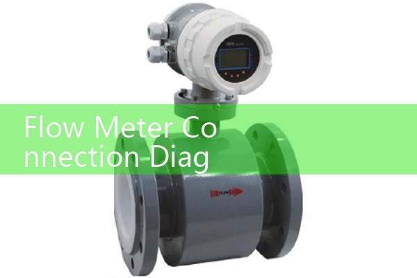
An electromagnetic flow meter must be at the same potential as the liquid and the earth. For metal pipes with a conductive liner, use copper straps from the meter body to the upstream and downstream flanges. Keep the strap resistance below 10 ohm and the length below 5 m.
For PTFE, rubber, or painted pipe liners, install ground rings or grounding electrodes. Mount the ground rings between the flanges. Connect both rings to the meter ground terminal with a dedicated conductor. Do not rely on pipeline bolts. Paint, rust, and gasket contact cause high resistance.
In plants with heavy VFD interference, use a 16 mm2 copper strap instead of a thin wire. Silver Instruments supplies ground rings in 316L, Hastelloy C, titanium, and tantalum for pipe sizes from DN10 to DN600.
For a seawater desalination plant, use an electromagnetic flow meter with titanium electrodes and a PTFE liner. Ground rings are mandatory because seawater is conductive and stray currents in the pipe can be strong. Silver Instruments can size the correct seawater flow meter for desalination plant duty from DN25 to DN1000.
Power Loop Design for 4-20 mA and HART
Most two-wire flow meters need a DC supply. A 24 V DC supply is standard. The loop resistance limit is simple. Use Rmax = (Vsup - Vtx min) / 0.022. If the transmitter needs at least 12 V and the supply is 24 V, Rmax equals 545 ohm.
If you add a 250 ohm resistor for HART communication, subtract that from the budget. At 22 mA, a 250 ohm resistor drops 5.5 V. The transmitter still sees 18.5 V from a 24 V supply. That leaves 295 ohm for the cable and any barriers.
A 500 m loop with 0.75 mm2 copper cable adds about 22 ohm. Cable length is rarely the limiting factor for local control panels. The problem is usually too many loop devices or an undersized supply. Use a clean DC supply, not the same terminals that feed contactors or solenoid valves.
Cable Routing and Shield Termination
Route 4-20 mA signal cable in shielded twisted pair. Keep it at least 300 mm away from AC power, VFD output, and motor cables. Cross at right angles when separation is not possible.
Ground the shield at one end only. The best point is the PLC or control panel earth. Grounding both ends can create a ground loop and inject 50 Hz or 60 Hz noise. For RS485 Modbus wiring, use a daisy chain bus and a 120 ohm termination resistor at the last device.
Use metal cable glands and keep the shield as close to the terminal
Step by Step Connection Procedure
1. Confirm the supply voltage. Silver Instruments electromagnetic and Coriolis meters accept 24 V DC or 85 to 265 V AC depending on the version.
2. Check the terminal drawing for power, 4-20 mA, pulse, and Modbus terminals. Do not mix signal ground with protective earth.
3. Install ground rings or grounding electrodes if the pipe is lined or non-conductive. Connect them to the meter earth terminal.
4. Calculate the loop resistance with the formula above before adding a HART resistor or loop powered display.
5. Set the PLC or controller input to 4-20 mA. If the input is 0-10 V, add a 500 ohm precision resistor at the analog input. The resistor converts 4-20 mA to 2-10 V.
6. Power the loop and check the current with a multimeter in series. At zero flow, the output should sit near 4.00 mA. At span, it should sit near 20.00 mA.
Common Field Faults We See in Asia and Latin America
A 4-20 mA signal stuck at 3.8 mA often means a broken loop. A signal stuck at 21.5 mA often means a short or a transmitter in fault mode. A reading that drifts when a pump starts is usually a grounding problem.
Many plants connect a 4-20 mA flow meter to a PLC input set for 0-10 V without a resistor. The reading becomes unstable or sits near zero. One customer in Indonesia replaced a flow meter twice before we found the PLC input range was wrong. The real fix was adding a 500 ohm resistor and changing the input type.
Most engineers skip the power budget. Here is the thing. A loop powered display, a HART resistor, a barrier, and a long cable can push the total resistance past 545 ohm. The transmitter then drops out at high flow when it needs more current.
FAQ: Five Wiring Questions That Come Up Most
Q1: Should I ground both ends of the 4-20 mA shield?
A: No. Ground one end only, usually at the PLC or panel. Grounding both ends can create a ground loop. In rare long distance applications with full equipotential bonding, a second end may be connected through a capacitor. Most sites should stick to one end.
Q2: What is the maximum cable length for a 4-20 mA loop?
A: It depends on the cable resistance and the supply voltage. For a 24 V DC supply and 0.75 mm2 cable, 500 m to 1000 m is usually acceptable. Calculate the total loop resistance and keep it below the transmitter limit.
Q3: Do I need ground rings for an electromagnetic flow meter on a plastic pipe?
A: Yes. Use ground rings or grounding electrodes. Without them, the liquid may not be at the same potential as the meter body. The reading can drift, freeze, or jump when nearby equipment starts.
Q4: Can I share one 24 V DC supply across several flow meters?
A: Yes if the total current is within the supply rating and each loop is fused separately. Do not daisy chain the signal loops. Keep each 4-20 mA loop isolated and run separate cable pairs.
Q5: What supply voltage does a Silver Instruments Coriolis meter need?
A: Most versions accept 24 V DC or 85 to 265 V AC. Check the terminal diagram on the nameplate. For field mounted units in ATEX Zone 1, follow the certified wiring diagram exactly.
Get a Wiring Diagram for Your Process
Send us your fluid, pressure (bar), temperature (°C), pipe size (DN), and flow range. Also tell us the supply voltage at the panel and the controller input type. The engineering team at Silver Automation Instruments will return a marked-up connection diagram and a quotation within one working day.
Silver Automation Instruments
Tel: +86-25-68650347
Whatsapp: +86-25-52155837
WeChat: +86 15365082610
 Hot Product
 Related AD