

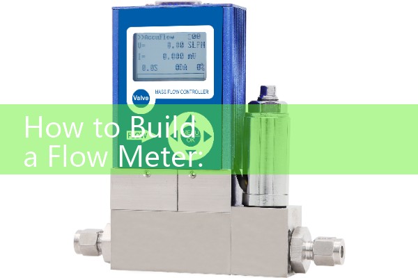
『How to Build a Flow Meter: Assemble an inline Hall-effect sensor with a microcontroller, then program it to count incoming pulse intervals.』Related information(v cone flow meter|rotary gas meter|gallon meter|gear meter|metal tube rotameter|glass tube rotameter|nutating disk meter|transit time ultrasonic flow meter|wedge flow meter|pd meters|hydraulic flow meter|ultrasonic water flow meter|water flow meter|air flow meter|magnetic water flow meter|oxygen flow meter|gas flow meter|argon flow meter|air velocity meter|gasoline flow meter|fuel flow meter|ultrasonic water meter|digital water meter|nitrogen flow meter|solid flow meter|Oxygen tank flow meter|digital water flow meter|diesel fuel flow meter|steam flow meter|02 flow meter|compressed air flow meter|oil flow meter|liquid flow meter)
How to Build a Flow Meter with an Inline Hall-Effect Sensor and a Microcontroller
Quick Answer: An inline Hall-effect flow sensor with a pulse output and a microcontroller is enough for clean water flow measurement up to about 30 L/min. Wire the signal wire to a digital interrupt pin. Program the microcontroller to count pulse intervals and convert pulse frequency to flow rate using the sensor K factor. For industrial fluids, high pressure, or custody transfer, use a dedicated flow meter from Silver Automation Instruments.
What You Need for a Hall-Effect Flow Meter Build
You need three main parts. First, an inline Hall-effect turbine flow sensor such as a YF-S201, YF-B1, or similar DN15 to DN20 module. Second, a microcontroller board such as an Arduino Uno, ESP32, or STM32. Third, a 5 V DC power supply with at least 50 mA headroom. Most low cost Hall-effect sensors draw 10 mA to 15 mA and output a square wave pulse.
Wiring the Inline Hall-Effect Sensor to a Microcontroller
Connect the red wire to 5 V DC. Connect the black wire to ground. Connect the yellow or white signal wire to digital pin 2 on the Arduino. If the sensor output is open collector, add a 10 kOhm pull-up resistor between the signal wire and 5 V. Keep the wire run under 2 m where possible. Longer runs pick up motor drive noise. Use shielded cable for cable runs over 5 m.
Programming Pulse Interval Counting
Set the digital pin as INPUT_PULLUP. Attach an interrupt on the rising edge of the pulse. In the interrupt service routine, record the micros timestamp and increment a pulse counter. Calculate the period between two rising edges. Convert period to frequency in Hz. Use the K factor from the sensor data sheet. For a YF-S201 sensor, the K factor is about 2.25 mL per pulse or 450 pulses per liter. Flow rate in L/min equals frequency in Hz multiplied by 60 divided by pulses per liter. Total volume equals pulse count divided by pulses per liter.
In practice, do not use long print statements inside the interrupt. That adds jitter and slows down pulse capture. Store the timestamp and let the main loop handle serial output.
Calibration and Accuracy Limits
Most engineers skip this part. Calibration still matters because K factor changes with flow profile, fluid temperature, and sensor wear. Fill a 10 L container and pass it through the sensor. Record the total pulse count. Divide total pulses by 10 to get actual pulses per liter. Repeat this at three flow rates such as 3 L/min, 8 L/min, and 15 L/min. You will see a slight non-linearity at low flow. Below 2 L/min a low cost rotor can stall. Above 25 L/min the pulse signal can become noisy.
When a DIY Flow Meter Makes Sense
This build fits clean water tests, cooling water loops, irrigation trials, and low pressure air flow checks. It is not suitable for corrosive chemicals, seawater, steam, food grade processes, or any fluid above 60 °C and 1.6 MPa. Plastic sensor bodies can crack or swell with solvents. The output is a raw pulse signal
Industrial Flow Meter Alternative from Silver Automation Instruments
Silver Automation Instruments supplies industrial flow meters for water, wastewater, oil, gas, chemical, and food plants. A customer in Vietnam used a DN50 electromagnetic flow meter to monitor brine at a desalination plant. A paint manufacturer in Southeast Asia replaced a plastic rotor meter with an oval gear flow meter for solvent batching. For compressed air at 7 bar, a vortex flow meter with 4-20 mA HART output is a common choice in the Philippines and Indonesia.
If your liquid is conductive, choose an electromagnetic flow meter for accuracy from 0.2% to 0.5% of reading. For water and wastewater applications, a DN50 electromagnetic flow meter with 4-20 mA HART and accuracy of 0.5% of reading is a solid replacement for a DIY Hall-effect setup. If you measure diesel, fuel oil, or high viscosity fluids, use an oval gear flow meter. For diesel from 0.5 L/min to 200 L/min, an oval gear flow meter with aluminum body and pulse output works well. If you measure steam, compressed air, or natural gas, a vortex flow meter works better than a Hall-effect build. For direct mass flow of oil and gas, a Coriolis mass flow meter from Silver Automation Instruments provides density and temperature data on the same loop.
Send us your pressure (bar), temperature (°C), pipe size (DN), and flow range. Our engineers will recommend a model and a quote within 24 hours.
FAQ
Can I use a Hall-effect flow meter for diesel?
Diesel can damage the plastic rotor and seals in low cost Hall-effect sensors. Use an oval gear flow meter with an aluminum or stainless steel body. Silver Automation Instruments supplies oval gear flow meters for diesel from 0.5 L/min to 200 L/min.
What accuracy can I expect from this DIY build?
Expect 3% to 5% of reading with a YF-S201 after calibration. Industrial electromagnetic flow meters from Silver Automation Instruments reach 0.2% to 0.5% of reading over a wider temperature range.
Which microcontroller is best for pulse interval counting?
An ESP32 or STM32 gives better timing resolution than an 8-bit Arduino Uno. Use hardware timer capture mode if possible. This reduces timing jitter from interrupt latency.
How do I convert pulse count to total volume?
Divide the pulse count by pulses per liter. For a sensor with 450 pulses per liter, 900 pulses equals 2 L. Check the data sheet because K factors vary between sensor models.
When should I choose a commercial flow meter instead of this build?
Choose a commercial flow meter when the fluid is corrosive, hot, pressurized, or used for billing or batch control. An industrial flow meter with 4-20 mA HART, RS485, and a local display is easier to integrate into a PLC or SCADA system.
Contact Silver Automation Instruments. Tel +86-25-68650347. WhatsApp +86-25-52155837. WeChat +86 15365082610.
 Hot Blog
 Related AD